Home automation: reading my IZAR WMBus PRIOS hot water smart meter
Exploration, trial and error, reverse engineering, and key cracking
Introduction
My current condo in Lyon has two separate water sources:
- Cold water, provided by the city utility department (a part public, part private company).
- Hot water, which is heated from solar panels on the roof of the building, with natural gas being burned for the rest of the required energy.
Both these streams are metered separately and individually for each condo. It’s now required by law in France that collective HVAC systems have to be billed independently for each consumer, to prevent abuse from a minority of people (reference: Copropriété : individualisation des frais de chauffage et de refroidissement 30 octobre 2019 - Direction de l'information légale et administrative.)
So how is my hot water metered?
Part 1: Discovering the setup
Following the pipes I managed to find this meter in one of my utility closets:
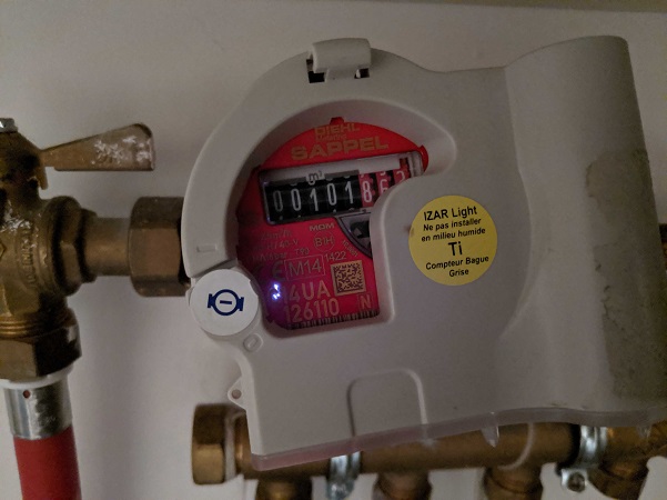
The contraption is made of two parts:
- The water meter.
- The IZAR module.
The water meter
The water meter, i.e. the actual device counting how many liters go through the pipe, was made from SAPPEL, a century old French company that was merged with other German companies over time to create DIEHL Metering, the actual company making the part now.
The closest one I could find on their product catalog is the “ARIES DN15/20”:
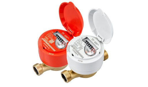
As we’ll see later, knowing the precise actual model is not important.
This thing is counting the water volume, and then an additional module is clipped on top of it to transmit the measurements someplace else.
The IZAR module
Clipped on top of the water meter is an IZAR module. Those modules read and count the ticks generated by the ARIES meter, and allows the values to be stored into or broadcasted to other systems.
The model my counter has is an IZAR RC 868 I RA LIGHT, which is coincidently also made by SAPPEL/DIEHL Metering.
The closest I could find on their catalog is the IZAR RC I R4. Those modules store the measurements of the meter and broadcast them wirelessly over the 868MHz license free radio range. This is consistent with the fact that ever since I’ve been living in that condo, no one has even come to my place to read the meter, and I’ve never input the values anywhere. Still, I was billed correctly at the end of each fiscal year. The values have been transmitted wirelessly to a receiving device owned by the company handling the collective hot water furnace of my building.
There are two usual ways this is done:
- If the data collection company is owned by the city utility service and most building are equipped with the same technology, receiving equipment is permanently installed every few building on top of lampposts or anywhere an antenna fits, and all meters transmit their measurements a few times a day.
- If having permanent collection antennas is impossible or not worth the investment, meters usually transmit their measurements more frequently (from once to a few seconds to a couple minutes) and collection agents periodically move close the building and collect all values at once. This can be company agents moving around with a handheld device, garbage collection trucks with an antenna on top of the truck, or anything else capable or reading radio waves coming close to the building.
Great. Now, let’s find out what system my meter is using, and collect the values myself.
Part 2: Finding how the data is transmitted
The name of the device (RC 868 something) and the datasheet indicates 868MHz radio waves are used, which makes sense since that radio range is typically used for these kind of devices (along with the 433MHz ISM range).
Since I worked on this project during the covid-19 lockdown in spring 2020, I didn’t have access to any spectrum analyzer. So it’s time for some good old fashioned internet research.
First, let’s have a look at the datasheet of the IZAR RC I R4. It’s not exactly the model I have, but browsing the entire product catalog of DIEHL Metering, it seems that their receiving technology didn’t change in the last years. So I’ll assume this newer model has the same technology.
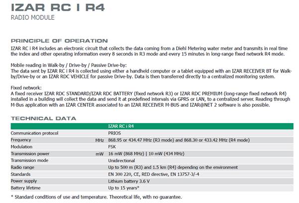
Frequency of operation
The description of the module explain that the measurements are made to be read by a passing-by receiver. This means that we should see radio waves periodically, which has great advantages:
- Trial and error is much better with one radio frame every 15mn than once a day.
- I’ll be able to monitor my hot water consumption with at least 15mn increment precision, which is going to give great data once I correlate this with my inside and outside temperature readings, along with the commands I already send wirelessly to my radiators.
The device has an internal battery which is supposed to last 15 years.
Protocols
The datasheet says the communication protocol is named "PRIOS". Unfortunately, this is a private internal protocol of DIEHL Metering, and no documentation is provided anywhere.
Let’s read more:
“Reading through M-Bus application with an IZAR CENTER associated to an IZAR RECEIVER M-BUS is also possible”.
“ZAR RECEIVER M-BUS is used for fixed network reading of meters equipped with an IZAR radio. It converts the data into M-Bus format and transmits them to an IZAR CENTER M-Bus master.”
Could this be Wireless M-Bus? That’d be great. This thing is a standard protocol and documentation exists about it.
Let’s look at the standards the device is compliant with:
- CE: I live in the EU, so that’s always nice to have.
- RED directive and EN 300 220: Ok, this thing’s radio waves will not kill me or disturb other communications. Good
- EN 13757-3/-4: EU norm for “Communication systems for meters”. Now, this is interesting!
Quoting the description of the norm:
“It consists of 9 documents. M-Bus (Meter-Bus) is a European standard (EN 13757-2 physical and link layer, EN 13757-3 application layer) for the remote reading of gas or electricity meters. M-Bus is also usable for other types of consumption meters. The M-Bus interface is made for communication on two wire, making it very cost effective. A radio variant of M-Bus (Wireless M-Bus) is also specified in EN 13757-4. The DLMS/COSEM standard suite (IEC 62056 / EN 13757-1) is the most widely accepted international standard for utility meter data exchange.”
Ok, if the datasheet doesn’t lie, we’re definitely dealing with Wireless M-Bus here. What a relief. My guess now is that everything in the protocol stack up to the application level is WMBus, and PRIOS is the business payload transmitted on top (i.e. the device’s measurements).
During my research I also found the specifications of a protocol named “Open Metering System Specification”, which is a European Union normalization club for smart meter companies. Its goal, among others, is that companies providing utilities such as gas or water can use measuring and receiving equipment in a nice interoperable fashion. I have a very good opinion of this initiative. Standards are good. Normalization is good.
Looking at the member list of this club indicates that DIEHL Metering is a part of it. If the manufacturer of my smart meter is part of the EU normalization club for smart meters, then I should be able to use the documents provided by the club (specifications, protocols, etc.)
Let’s sum up what we should see going up the stack:
|
Layer |
Norm |
Reference document |
|---|---|---|
|
Application layer |
PRIOS protocol |
N/A |
|
Data Link |
Wireless M-Bus DLL (format of the frames). |
|
|
Physical Link |
Wireless M-Bus PHY |
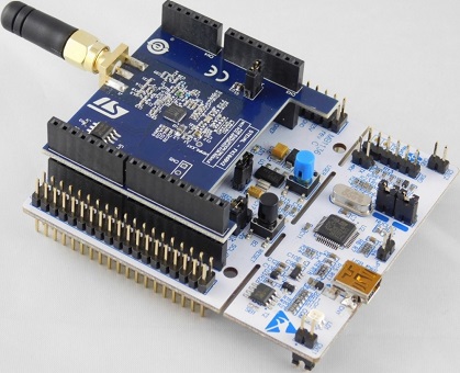
In order to test everything here and start doing measurements, I bought a STEVAL-FKI868V2 kit from ST-Micro (a NUCLEO-L053R8 board with a S2-LP 868MHz transceiver). I should be able to program those two boards to experiment with the different layers, and hopefully get my data.
Part 3: Going up the stack – Physical Link Layer
Gathering information
Let me rant for a bit first. I don’t care if private companies invent their own norms and license them for money. Your money, your norms, your price.
But here we’re talking about European Union standards. This was funded with public money and is supposed to apply to all EU countries. So why the f*ck am I supposed to pay 500€ per document?!? (6 of them). And I can’t get a PDF? This thing is made for the people by the people. Why the hell would I need to pay 1000s of euros to get a f*cking ton of paper delivered to my place. Come on EU! You can do much better than that!
So now we know we can’t read the actual standard. What do we do? We browse the internet and collect data from multiple places.
I’ve sourced the following data from 3 types of places:
- Datasheets of WMBus compatible hardware parts.
- Research papers done by students about smart metering.
- Source code of already existing WMBus implementations (even though they mostly contained the information for layers above the physical ones).
In the end this is what I found:
The physical layer of WMBus can work in a lot of different modes, each one for a specific type of business usage.
The OMS specs helps us filtering the list:
- “As for the various modes described in [EN 13757-4:2013], only the modes S1, S2, T1, T2, C1 and C2 are supported by this specification”
- “S1, T1 and C1 are unidirectional modes where the meter frequently (seconds to hours) transmits datagrams containing meter identification together with metered data.”
- “S2, T2 and C2 are compatible bidirectional enhancements of the respective unidirectional modes.”
My meter is unidirectional (according to its datasheet, and according to the fact it’s going to use the same battery charge for 15 years), so we know it’s only going to be mode S1, T1 or C1.
C1 is made for stationary operation, and we know my meter is drive-by, so it’s either S1 or T1.
Layer format
Here is the information I gathered for those two modes:
|
Information |
Mode S1 |
Mode T1 |
|---|---|---|
|
Frequency |
868.3MHz |
868.95MHz |
|
Modulation |
FSK |
FSK |
|
Data rate |
32.768kpbs |
100kbps |
|
Coding |
Manchester |
3 out of 6 |
|
Sync mechanism |
Preamble + Sync word |
Preamble + Sync word |
|
Preamble |
“01b” times 279 |
“01b” times 19 |
|
Sync word |
000111011010010110b |
0000111101b |
I’m going to dig into details about the modulation and encoding part of the layer here. Information about FSK modulation and Manchester/3-out-of-6 encoding is available easily on the internet and in books.
So, here’s what the binary data received is supposed to look like:
S1 mode:
|
Whatever happens before the start of the frame |
“01” times 279 |
Sync word |
Data |
|---|---|---|---|
|
xxxxxxxxx |
01010101010101..0101010101 |
000111011010010110 |
yyyyyyyyyyyy |
T1 mode:
|
Whatever happens before the start of the frame |
“01” times 19 |
Sync word |
Data |
|---|---|---|---|
|
xxxxxxxxx |
01010101010101010101010101010101010101 |
0000111101 |
yyyyyyyyyyyy |
Alright, that’s all we need to know. Let’s move up the stack.
Part 3: Going up the stack – Data Link Layer
The WMBus standard tells us which fields are present in the DDL, and the OMS specs tells us what to expect in each field.
The WMBus Data Link Layer (DLL) format
There are two possible formats allowed by the protocol. Frame format A and Frame format B.
Here what they look like:
Frame format A:
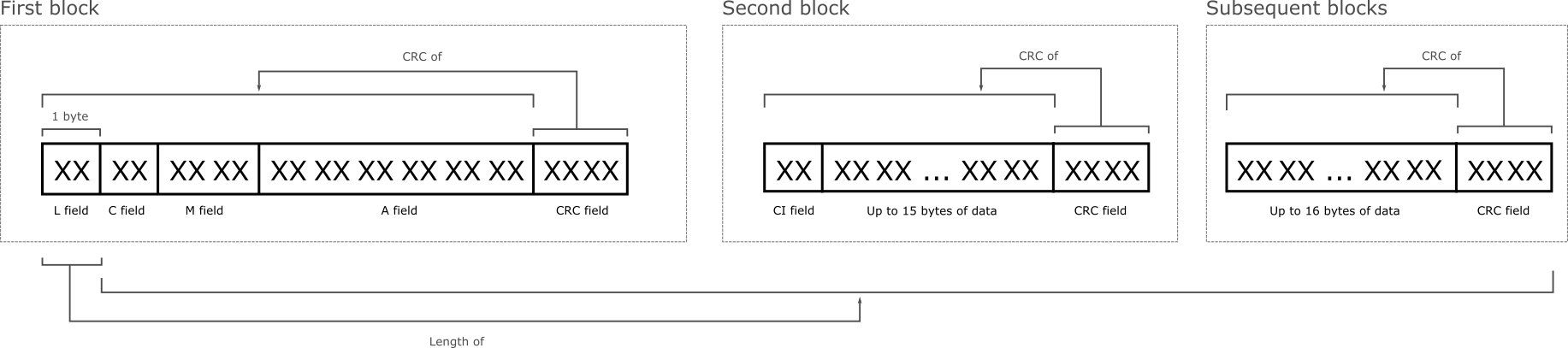
Frame format B:
Frame format B is very similar to Frame format A, but since I didn’t actually see any of them in the wild, I’m not going to risk documenting them here (spoiler alert: my meter is using format A).
Here are the different fields of the DLL:
|
Field name |
Length |
Comment |
|---|---|---|
|
L: Length |
1 byte |
Length of the entire frame except 1 byte (the L field) |
|
C: Control |
1 byte |
Type of the frame |
|
M: Manufacturer |
2 bytes |
ISO 646 code of the sender |
|
A: Address |
6 bytes |
Identifier of the sender |
|
CRC |
2 bytes |
CRC code of the preceding data |
|
CI: Control Information |
1 byte |
Type of protocol used by the data |
|
Data |
N bytes |
Upper layer data |
Fields in the context of the OMS
The Open Metering System specs contains a list of allowed values for the C-field. Most of them describe how meters should communicate bidirectionaly with a collector. Since my meter doesn’t have a receiving antenna, this limits the communications to only one frame type:
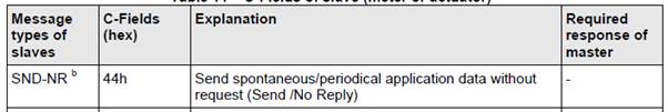
So field C should only be 0x44.
The address field format is not up to manufacturers as well. It’s composed of 3 fields:

Allowed device types are listed in the OMS standard document (Water meter = 0x07, Hot water meter = 0x15, etc.)
Part 4: Collecting frames from the meter
Collecting frames
Before digging into the application layer of the stack, it’s time to capture some frames.
I won't go into into much details about the 2 full days I spent trying to configure the microcontroller and the transceiver of my ST kit until I was able to properly capture frames. Part of the reason it took so long includes:
- The first diagnostic/demo tool provided by ST (supposed to be a WMBus sniffer) simply doesn’t work at all. It never captured anything in any combination of the possible settings.
- The second diagnostic/demo tool provided was capturing too much noise and thus I couldn’t see the actual frames in the middle of the junk. I live in the middle of France’s second largest city and the 868MHz band is loaded with a lot of things. Capturing WMBus frames involved capturing everything that managed to start with the preamble and sync code and checking if the data looks like a proper frame with correct CRCs.
After a super long time fiddling around, I managed to capture some frames that look like proper WMBus frames. I got them in T1 mode (868.95MHz, 80kHz deviation, 350kHz filter bandwidth, -100dbm RSSI threshold).
Here are a couple examples:
534424232004657378497AF75045DD994CA92728324EFDCA7E580BC520A370551739EE7CA880B04D55083968703A8983DBA30302071482A49AB9A99281BC86013892E579C0A4FC3880AD26DC1E5AFE1A57BC43AC

44304CC697D720D401E2E6A213120013184587BD6EB979401E8B407096
Let’s decode their link layers:
|
Description |
First frame |
Second frame |
|---|---|---|
|
L field |
53 |
19 |
|
C field |
44 |
44 |
|
M field |
2423 |
304C |
|
A field |
200465737849 |
C697D720D401 |
Let’s decode the M fields:
|
Description |
First frame |
Second frame |
|---|---|---|
|
Data (little endian) |
0x2423 |
0x304C |
|
The represented number in binary |
01000 11001 00100 |
10011 00001 10000 |
|
Each 5 bits block in decimal |
8 25 4 |
19 1 16 |
|
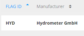
Letters corresponding to each number (A=1, B=2, Z=26) |
H Y D |
S A P |
It’s easy to guess what HYD and SAP stand for, but let’s look them up in the flag database of the Device Language Message Specification consortium:
https://www.dlms.com/flag-id/flag-id-list
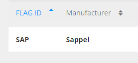
Since my meter was manufactured by Sappel, it’s quite obvious which frames I should investigate further.
Decoding a Sappel frame
Let’s look at a full frame received by the antenna of my circuit:
01010101010101010101010101010101010101 0000111101b + 1944304CC697D720D401E2E6A213120013184587BD6EB979401E8B407096h
|
Data |
Description |
Layer |
|---|---|---|
|
01010101010101010101010101010101010101 0000111101 (binary) |
T1 preamble + sync word |
Physical |
|
19 |
L-field, length of the frame |
Link |
|
44 |
C-field, SND-NR: periodical data broadcast |
Link |
|
304C |
M-field, SAP = Sappel |
Link |
|
C697D720 |
A-field Id, identifier of the meter |
Link |
|
D4 |
A-field version |
Link |
|
01 |
A-field type, 01=non-standard application specific |
Link |
|
E2E6 |
CRC of 1944304CC697D720D401 |
Link |
|
A2 |
CI-field, application specific |
Link |
|
13120013184587BD6EB979401E8B40 |
Application data |
Application |
|
7096 |
CRC of the application data |
Link |
Right now I’m capturing the frames or a dozen Sappel meters, each of them sending its data about every minute. This is great. This means I should be able to plot my hot water consumption with a 1 minute interval. This is going to be great data!
Now, the problem is the application data is encrypted, and the actual protocol is not known. It’s time to move to the next step.
Part 5: the PRIOS protocol
How do we decrypt and decode the application payload?
First way: we look around and see if some has done it before
So it turns out one guy named Jacek Tomasiak already decoded the protocol and added the logic into an application called wmbusmeters:
I’ve copied his logic into my code, and I confirm it works great.
But let’s imagine this work hasn’t been done before and see if we can achieve it ourselves.
Second way: check if we can extract data from the receiver products
Looking for receiver solutions
DIEHL Metering provides a number of devices we can use to collect the radio waves from the meters. But since those are probably expensive (they’re not on the shelf products), I’m not going to buy one to check what’s inside.
What about software?
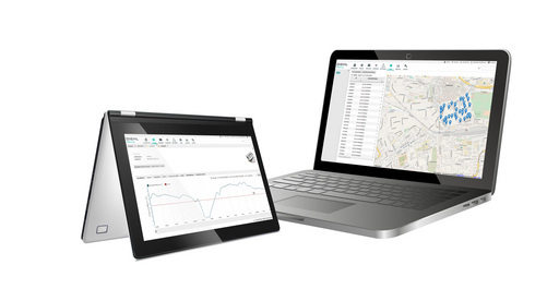
DIEHL provided a software solution to manage a fleet of meters in a city.
“Offers all the functionalities of MBUS reading solutions such as IZAR CENTER, either in direct connection (via RS232, USB, LAN) or in remote connection (modem) as well as the management and analysis of the data coming from MBUS meters.”
So, if this sentence is right, the logic to decode the WMBus frames should be somewhere in there. How do we get it?
Well, I didn’t see any download button anywhere, and I didn’t really wanted to waste the time of their salesman to schedule a trial (we’re in a pandemic right now), but fortunately, DIEHL provides an AMI on Azure with the whole thing already installed:
https://azuremarketplace.microsoft.com/en-us/marketplace/apps/diehl-metering.izarnet
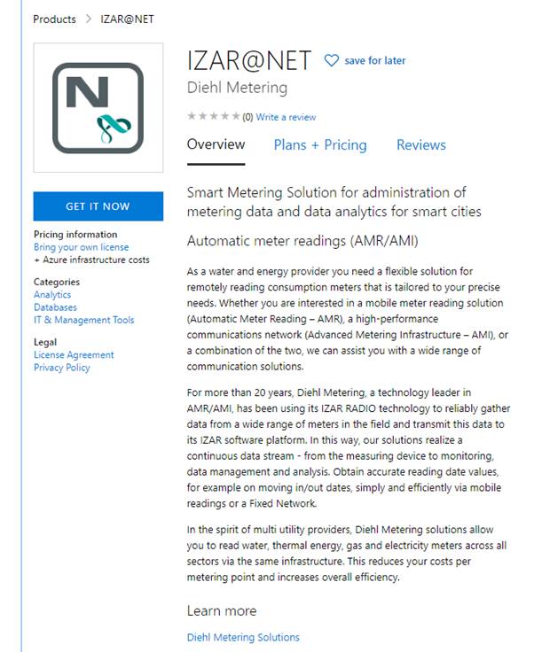
Let’s fire one and see what we can find inside.
I’m not going to go into great details about the exploration of the image since the application and its files are the property of DIEHL Metering and I don’t technically have a license for them. What I can say is that the whole system contains code to collect data via MQTT, multiple databases (Elasticsearch, Derby) and web apps for management.
Disassembling a dozen application packages lead me to discover the logic to decrypt and decode the PRIOS payloads.
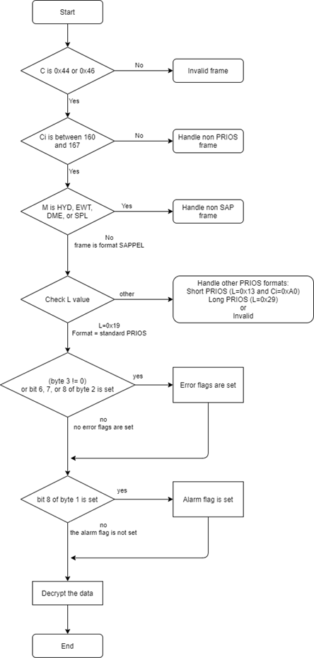
Extracting the logic and protocol
Here is the logic to detect the payload type and check for errors (only following the path for my specific meter):
Decrypting the data is done using XORs and a https://en.wikipedia.org/wiki/Linear-feedback_shift_register
I’m not going into details here. You can find my C implementation based on Jacek’s here:
Here’s the content of each part of the payload, with payload 13120013184587BD6EB979401E8B40 as an example:
|
Description |
Details |
Example value |
Example details |
|---|---|---|---|
|
Status field 1 |
Bit 8: general alarm. |
13 |
No general alarm. |
|
Status field 2 |
Bit 8: leakage currently. |
12 |
No leakage detected, meter is not blocked. |
|
Status field 3 |
Bit 8: back flow. |
00 |
No alarm set here |
|
Vif |
Identifies the unit of the measurement. |
13 |
00010b = volume in cubic meters. |
|
??? |
Always set to 4B, called “old IZAR specific config field” |
4B |
Set correctly |
|
Current reading |
4 bytes, current value measured by the meter |
47730200 |
47730200h = 160583d. |
|
H0 reading |
4 bytes, historical value measured by the meter |
8A6D0200 |
8A6D0200h = 159114d. |
|
H0 date |
2 bytes, contains the date of the H0 reading. |
8124 |
2020-04-01, the beginning of the month when this frame was captured. |
Only the 4B field and the readings and the H0 date are encrypted. The 4 first bytes, called the header, are plain text.
But wait? How did I decrypt the data if I only knew the encryption algorithm? Shouldn’t there be a key?
Yes there is. But embedded into the code of the IZAL collector was the two “PRIOS default keys”. And turns out all the meters in my building are using the first one! Talk about security!
Cracking the key
Let’s imagine for a second that the people who installed my meter did their job correctly and actually set a different key than the default one (if they could, maybe the device doesn’t support that, which would be even worse).
How do we find the key?
Easy: we gather a bunch of frames and we brute-force it.
We know the first byte is always 0x4B, the next 4 bytes and the next 4 bytes represent a monotonically increasing value (the second being lower or equal than the first), and the next 2 bytes encode a proper date.
But how long is this cracking going to be, you ask?
Well, if you look at the code, the first thing the key is used for is to create another key, with half the length of the original one:
uint32_t preparePRIOSKey(uint8_t *bytes) {
    uint32_t key1 = read_uint32_be(bytes, 0);
    uint32_t key2 = read_uint32_be(bytes, 4);
    uint32_t key = key1 ^ key2;
    return key;
}
Since the final key is only the first part of the 64 bit original key, XORed with the second part, we should be able to find a working 32 bit key out of the first 32 bits of our choice.
Here is a quick and dirty bunch of C for loops than can be used to find a key:
Here is the key originally used by my meter:
{0x39, 0xBC, 0x8A, 0x10, 0xE6, 0x6D, 0x83, 0xF8}
Here are a bunch of keys that work just as well, that I cracked from a list of captured frames:
{0xdf, 0xd1, 0x09, 0xe8, 0x00, 0x00, 0x00,0x00}
{0x01, 0x7c, 0xb7, 0x47, 0xde, 0xad, 0xbe, 0xaf}
{0x20, 0x2e, 0xf6, 0x17, 0xff, 0xff, 0xff, 0xff}
Each of them took a few minutes to find on modern PC computer.
Epilogue
So that’s it, we’re done identifying everything received by the antenna, from the physical synchronization to actual application data.
Here is the hot water consumption of a dozen random meters within my antenna's range:
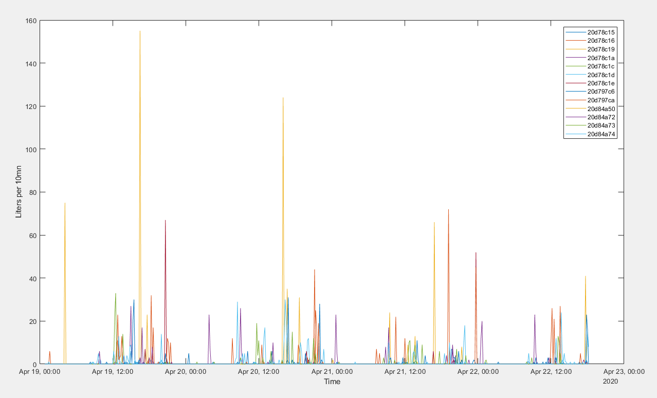
Fewer people shower on Sunday morning than on Monday morning.
This nice adventure can come to an end.
You can find my complete implementation for the ST kit here:
https://github.com/ZeWaren/izar-prios-smart-meter-collector
If you have a different PRIOS device than mine, or if you have the time and motivation to write a complete PRIOS decoding library, feel free to contact me for help.
Here are a couple pull requests I submitted to wmbusmeter:
- Support of the new data: https://github.com/weetmuts/wmbusmeters/pull/106
- FreeBSD support: https://github.com/weetmuts/wmbusmeters/pull/105